
My D18 build…
Warning: I wrote up a lot of shit. I know that some of you might be interested in the details. Skip to the build summary and pix if you can't bear to read it all.
This is a thread about building a 1.8l D16Y8 aka the D18 and installing into my 97 Hatch. While I’m still in the middle of this build, I thought I’d get started documenting what I’m doing and share my thought process behind it. Of course this is an open forum so all comments and question are welcome.
The Goal
My goal with this project is not to impress anyone with big HP numbers, sub 14 second ¼ mile times, or Mustang kill stories. My goal is to build an engine for a daily driver that is interesting and fun for me. I’m not trying to be “different” but rather I wanted to do a build that had new or at least uncommon challenges. Swapping in a bigger engine or slapping on a turbo kit is not interesting for me. Getting the most power for the least dollars is not important to me either. I’m mostly interested in the learning process. And I also like the idea of building what you have.
Still, I do have some design objectives. I will be using a D16 block and build it to make my daily commute more fun. The commute consists of winding hilly undivided “scenic” highways that travel through the CT country side. The max speed limit is 45mph which means I’ll get up to 60 in some areas especially when passing slower cars. Quick acceleration from a standstill or from slow speeds (without doing a launch) is important to me. Therefore, the overall goal is to maximize the low to mid-range powerband.
No replacement for displacement
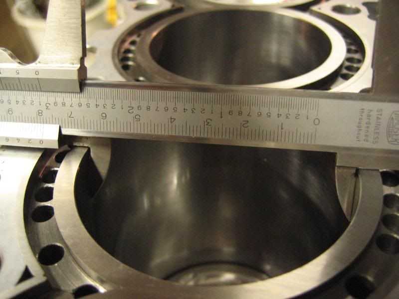
OK, so I’ve chosen to increase low end torque by reliably maximizing the displacement of the D16. This basically means I need to increase the bore and stroke. Now I’ve read on various forums of 81mm bored d-series motors but those engines apparently didn’t last nor could I find a way to do this reliably. I felt the safest approach to increase bore is to sleeve the block and bore to 78mm. Darton recommends this as a maximum bore for their d-series iron MID sleeves. So the build includes Darton open deck MID sleeves. So that’s pretty simple (but expensive).
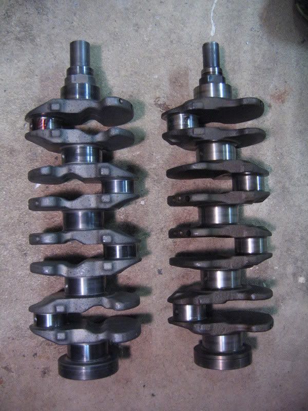
The most common way to stroke the D16 is to swap in a D17 crank. There are a few different ways to go about this part of the build. The problem with adding the D17 crank is that you need thinner rods to fit between the journals and you need to deal with the D17’s larger snout. You can choose between stock D17 rods, aftermarket D17 rods, B18C rods, or custom rods. Custom rods might be something to consider if you want to use standard D16 pistons. If you use standard 137mm rods with the D17 crank the longer stroke will clear the deck. So in this case you need to use pistons with the same (27mm) compression height as the D17. However, if you wanted to use D16 pistons that have a higher (29.5mm) compression height you could get custom shorter rods (134mm). The tradeoff is that 78mm D16 pistons are readily available but the R/S ratio (1.42) would be even less favorable than the stock D17 (1.45) but not by a whole lot. As a comparison the D16 R/S is 1.52. More on R/S ratio later.
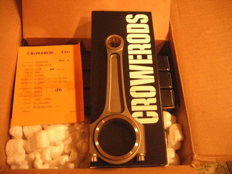
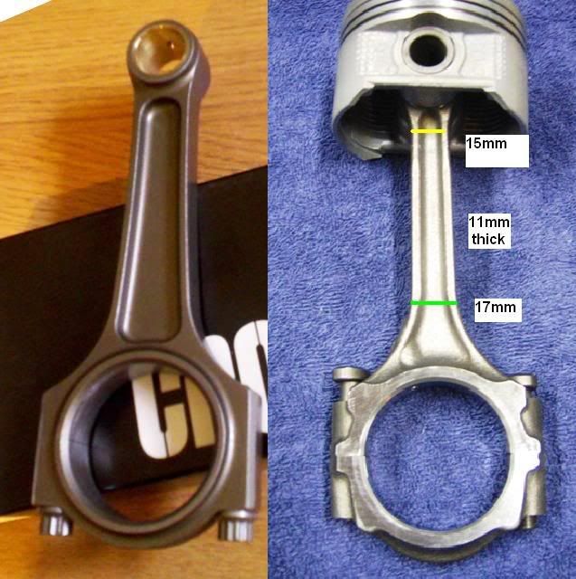
I chose to go with Crower maxi-lite I-beam D17 rods. At the time there were no other reasonable aftermarket options. They are a proven product and lighter than H beam rods (i.e. Eagle). OEM D17 rods have been known to hold up past 200 hp but as you’ll see in the pics they look really weak and I thought it better to build in some strength to the rotating assembly in case I decide to increase boost later. They are not cheap. Using B18C (137.9mm) rods is possible but some machining is required to narrow the BE so I thought it better to avoid possible mistakes made by a machinist or risk bearing fitment issues that could lead to spun bearings. B18C rods not only need the BE narrowed they also need custom piston work to deal with the 21mm PE diameter. The cost savings could get eaten up by the cost of machining. This might be a good option if you can machine them yourself.
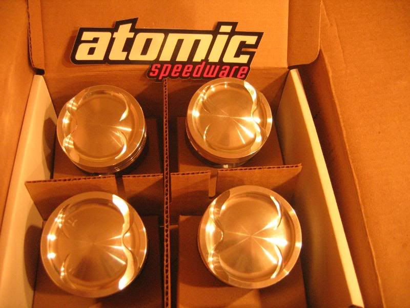
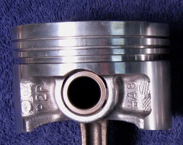
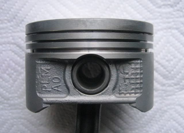
The pistons used in my build are custom 78mm Arias D17-like pistons designed by Nick Arias III from Atomic Speedware. The 6.22cc dish gives us a C/R of about 10.2:1 when installed in a stock D16Y8 with a .030” head gasket. The deck clearance is calculated to be -.032”. One thing that Nick changed was to move the oil ring down a bit. Doing this intersected the pin hole so buttons were used to form a continuation of the ring land through the pin hole. I didn’t get a pic of this, sorry! More on the C/R later.
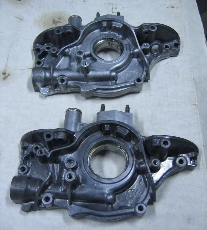
Now back to the crank snout… The D17 crank drops right into the D16Y8 block. The end caps of the D17 and D16Y8 look identical. The oil pumps look identical except for 2 things; the D17 has no dipstick hole and the oil seal opening is bigger. The dipstick problem can be avoided altogether when using a D16Z6 block since it’s located on the exhaust side of the block. Another option is to machine a dipstick hole in the D17 oil pump and use that pump (the D16Y8 oil pan bolts up to it fine). I chose to machine the crank so that a D16Y8 pump could be used – specifically a Toga high volume pump. You could have the D17 pump ported and shimmed to add oil pressure but I chose to go with an off-the-shelf product in the hopes of avoiding mistakes in the machine work.
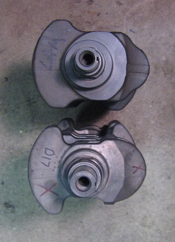
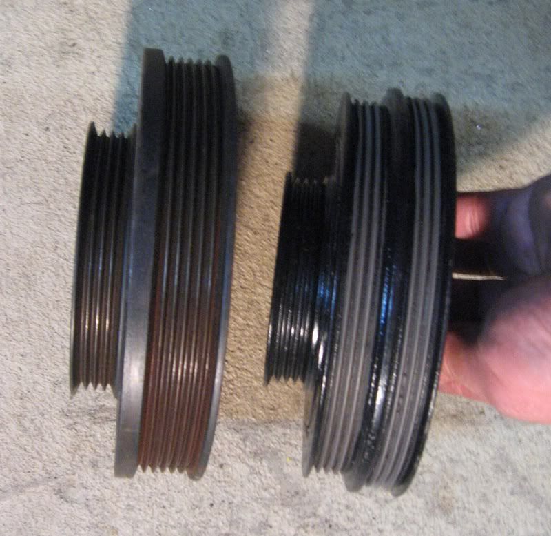
In addition, the diameter of the very end of the D17 crank snout is larger than the D16Y8. So the crank pulley and timing gear will not fit. You could use the D17 timing gear and pulley or have the D16Y8 gear and pulley machined. I chose to machine the snout so that I could use the stock D16Y8 parts and avoid any possible mechanical timing issues. I could use an aftermarket D16Y8 pulley if I chose (I know - at great risk to my bearings). The D17 crank pulley has more ribs on it so you’d have to get a special alternator pulley to match it, etc. So besides installing sleeves the only special machine work so far was done to the crank snout. I provided my machinist with a Y8 crank as a template. He also cleaned and polished the crank journals.
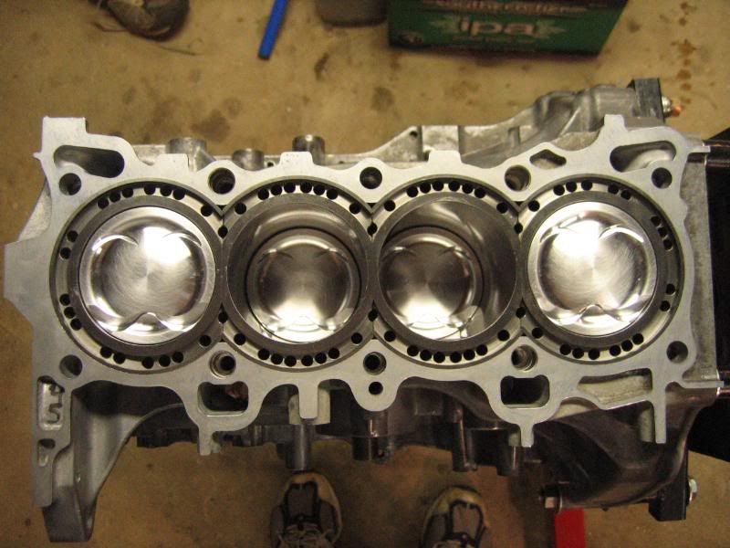
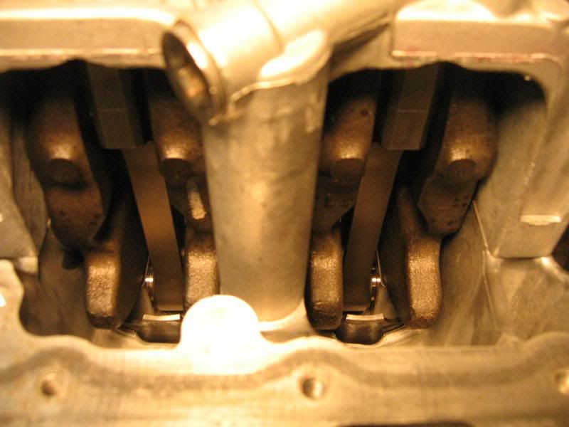
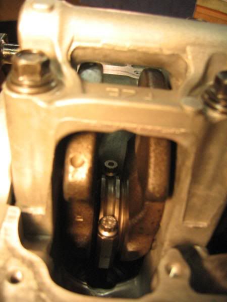
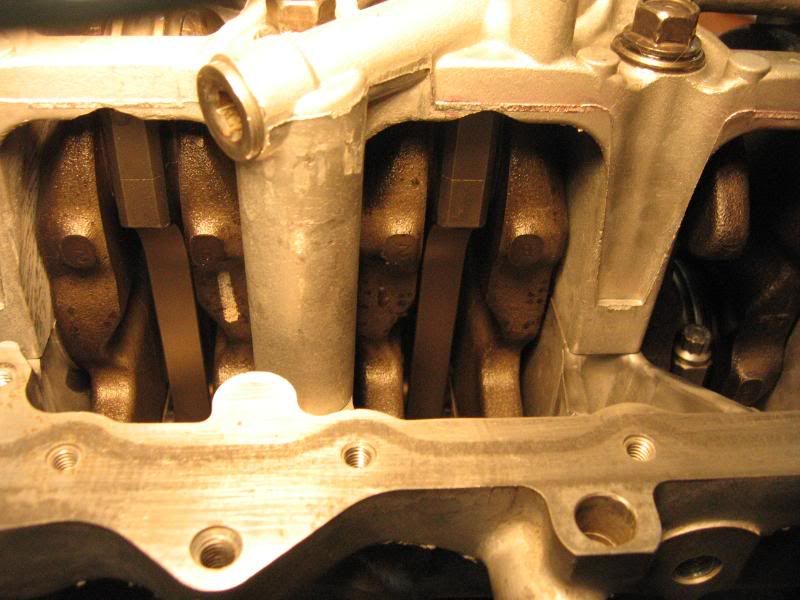
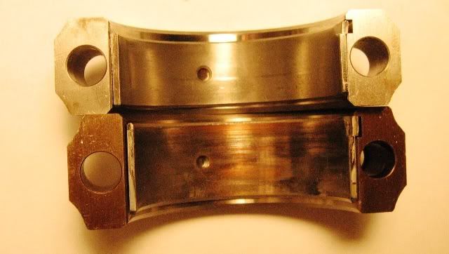
There were 2 other things that needed machining. Because larger aftermarket I-beam rods were used, the block needed notching as usually is the case. Secondly, the main cap had to be notched to accommodate the more extreme rod swing. See the pics.
Still I want even more torque
The plan is to build this motor N/A for the time being and get it running reliably. This coming winter I plan on adding a JRSC. This is one reason that the C/R of 10.2:1 was chosen. It is believed to be a good ratio for this blower. It is also relatively close to the stock compression of 9.6:1. I need to have the car pass an emission inspection that consists of an ODB2 scan for CELs. So I need to be able to run the engine briefly using the stock ECU. This is another reason I stuck with the D16Y8 – since the car is a 97 it needs to run ODB2 once every 2 years for this test. I didn’t want to dick around with older blocks with newer heads, mess with wiring, etc.
More on R/S ratios
OK I promised I’d touch on this again. The so-called poor geometry of Civic engines has been discussed with great conviction on this and other forums. I’m not a mechanical engineer but I am an engineer by trade so I see most design choices as having positive and negative trade-offs as opposed to black and white absolutes. In other words, some would say that the D17 geometry sucks because you can’t rev it so it ain’t any good. That’s nice but one of the positive trade-offs is that it has good low end torque. Good for me cause that’s what I want. What about excessive side-loading and higher piston acceleration speeds? Is side loading a problem in stock D16s? How much worse is it in a D17? I couldn’t find a way to calculate absolute side load force values (there are too many variables) but I did find a way to calculate the percentage increase in maximum side loading. You can calculate a “normalized” force generated by the combustion that gets directed to the cylinder wall at various crank angles. The maximum force occurs at about 75* from TDC. The D16Y8 calculated out to a normalized side wall force of .34 while the D17 came out to .35. That’s a 3% increase in side wall loading. This seems like a minimal increase to me so I’m not worried. Apparantly Honda wasn;t worried either when they built millions of D17s. For extra protection I also had the piston skirts coated. (If anyone’s interested on more details I can post up links to detailed discussions along with the spread sheet that does the calculations.)
Where will all this lead? How much HP? How many ft-lbs? Whatever it is – it is.
Continued...
Warning: I wrote up a lot of shit. I know that some of you might be interested in the details. Skip to the build summary and pix if you can't bear to read it all.
This is a thread about building a 1.8l D16Y8 aka the D18 and installing into my 97 Hatch. While I’m still in the middle of this build, I thought I’d get started documenting what I’m doing and share my thought process behind it. Of course this is an open forum so all comments and question are welcome.
The Goal
My goal with this project is not to impress anyone with big HP numbers, sub 14 second ¼ mile times, or Mustang kill stories. My goal is to build an engine for a daily driver that is interesting and fun for me. I’m not trying to be “different” but rather I wanted to do a build that had new or at least uncommon challenges. Swapping in a bigger engine or slapping on a turbo kit is not interesting for me. Getting the most power for the least dollars is not important to me either. I’m mostly interested in the learning process. And I also like the idea of building what you have.
Still, I do have some design objectives. I will be using a D16 block and build it to make my daily commute more fun. The commute consists of winding hilly undivided “scenic” highways that travel through the CT country side. The max speed limit is 45mph which means I’ll get up to 60 in some areas especially when passing slower cars. Quick acceleration from a standstill or from slow speeds (without doing a launch) is important to me. Therefore, the overall goal is to maximize the low to mid-range powerband.
No replacement for displacement
OK, so I’ve chosen to increase low end torque by reliably maximizing the displacement of the D16. This basically means I need to increase the bore and stroke. Now I’ve read on various forums of 81mm bored d-series motors but those engines apparently didn’t last nor could I find a way to do this reliably. I felt the safest approach to increase bore is to sleeve the block and bore to 78mm. Darton recommends this as a maximum bore for their d-series iron MID sleeves. So the build includes Darton open deck MID sleeves. So that’s pretty simple (but expensive).
The most common way to stroke the D16 is to swap in a D17 crank. There are a few different ways to go about this part of the build. The problem with adding the D17 crank is that you need thinner rods to fit between the journals and you need to deal with the D17’s larger snout. You can choose between stock D17 rods, aftermarket D17 rods, B18C rods, or custom rods. Custom rods might be something to consider if you want to use standard D16 pistons. If you use standard 137mm rods with the D17 crank the longer stroke will clear the deck. So in this case you need to use pistons with the same (27mm) compression height as the D17. However, if you wanted to use D16 pistons that have a higher (29.5mm) compression height you could get custom shorter rods (134mm). The tradeoff is that 78mm D16 pistons are readily available but the R/S ratio (1.42) would be even less favorable than the stock D17 (1.45) but not by a whole lot. As a comparison the D16 R/S is 1.52. More on R/S ratio later.
I chose to go with Crower maxi-lite I-beam D17 rods. At the time there were no other reasonable aftermarket options. They are a proven product and lighter than H beam rods (i.e. Eagle). OEM D17 rods have been known to hold up past 200 hp but as you’ll see in the pics they look really weak and I thought it better to build in some strength to the rotating assembly in case I decide to increase boost later. They are not cheap. Using B18C (137.9mm) rods is possible but some machining is required to narrow the BE so I thought it better to avoid possible mistakes made by a machinist or risk bearing fitment issues that could lead to spun bearings. B18C rods not only need the BE narrowed they also need custom piston work to deal with the 21mm PE diameter. The cost savings could get eaten up by the cost of machining. This might be a good option if you can machine them yourself.
The pistons used in my build are custom 78mm Arias D17-like pistons designed by Nick Arias III from Atomic Speedware. The 6.22cc dish gives us a C/R of about 10.2:1 when installed in a stock D16Y8 with a .030” head gasket. The deck clearance is calculated to be -.032”. One thing that Nick changed was to move the oil ring down a bit. Doing this intersected the pin hole so buttons were used to form a continuation of the ring land through the pin hole. I didn’t get a pic of this, sorry! More on the C/R later.
Now back to the crank snout… The D17 crank drops right into the D16Y8 block. The end caps of the D17 and D16Y8 look identical. The oil pumps look identical except for 2 things; the D17 has no dipstick hole and the oil seal opening is bigger. The dipstick problem can be avoided altogether when using a D16Z6 block since it’s located on the exhaust side of the block. Another option is to machine a dipstick hole in the D17 oil pump and use that pump (the D16Y8 oil pan bolts up to it fine). I chose to machine the crank so that a D16Y8 pump could be used – specifically a Toga high volume pump. You could have the D17 pump ported and shimmed to add oil pressure but I chose to go with an off-the-shelf product in the hopes of avoiding mistakes in the machine work.
In addition, the diameter of the very end of the D17 crank snout is larger than the D16Y8. So the crank pulley and timing gear will not fit. You could use the D17 timing gear and pulley or have the D16Y8 gear and pulley machined. I chose to machine the snout so that I could use the stock D16Y8 parts and avoid any possible mechanical timing issues. I could use an aftermarket D16Y8 pulley if I chose (I know - at great risk to my bearings). The D17 crank pulley has more ribs on it so you’d have to get a special alternator pulley to match it, etc. So besides installing sleeves the only special machine work so far was done to the crank snout. I provided my machinist with a Y8 crank as a template. He also cleaned and polished the crank journals.
There were 2 other things that needed machining. Because larger aftermarket I-beam rods were used, the block needed notching as usually is the case. Secondly, the main cap had to be notched to accommodate the more extreme rod swing. See the pics.
Still I want even more torque
The plan is to build this motor N/A for the time being and get it running reliably. This coming winter I plan on adding a JRSC. This is one reason that the C/R of 10.2:1 was chosen. It is believed to be a good ratio for this blower. It is also relatively close to the stock compression of 9.6:1. I need to have the car pass an emission inspection that consists of an ODB2 scan for CELs. So I need to be able to run the engine briefly using the stock ECU. This is another reason I stuck with the D16Y8 – since the car is a 97 it needs to run ODB2 once every 2 years for this test. I didn’t want to dick around with older blocks with newer heads, mess with wiring, etc.
More on R/S ratios
OK I promised I’d touch on this again. The so-called poor geometry of Civic engines has been discussed with great conviction on this and other forums. I’m not a mechanical engineer but I am an engineer by trade so I see most design choices as having positive and negative trade-offs as opposed to black and white absolutes. In other words, some would say that the D17 geometry sucks because you can’t rev it so it ain’t any good. That’s nice but one of the positive trade-offs is that it has good low end torque. Good for me cause that’s what I want. What about excessive side-loading and higher piston acceleration speeds? Is side loading a problem in stock D16s? How much worse is it in a D17? I couldn’t find a way to calculate absolute side load force values (there are too many variables) but I did find a way to calculate the percentage increase in maximum side loading. You can calculate a “normalized” force generated by the combustion that gets directed to the cylinder wall at various crank angles. The maximum force occurs at about 75* from TDC. The D16Y8 calculated out to a normalized side wall force of .34 while the D17 came out to .35. That’s a 3% increase in side wall loading. This seems like a minimal increase to me so I’m not worried. Apparantly Honda wasn;t worried either when they built millions of D17s. For extra protection I also had the piston skirts coated. (If anyone’s interested on more details I can post up links to detailed discussions along with the spread sheet that does the calculations.)
Where will all this lead? How much HP? How many ft-lbs? Whatever it is – it is.
Continued...


")