
UPDATE- Chipping P08 ECU - DEFINITIVE info
Ok, as the title says, I need some confirmation on the chipping locations.
To give some clarity to the situation, I have a JDM Chipping Kit from xenocron that I bought. I've visited their tech pages and there is no definitive page I could find for a P08 ECU Chip [how to].
I found a link on PGMFI but that was for a P30 ECU. Ive also seen the one for the P28 in the DIY section but mine as expected is completely diferent.
What I know:
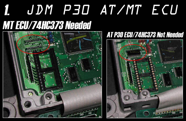
![Image]()
I've got install the DIP socket, the chip for the area circled [see above] and the 4 pin CN Datalogging Header. Thats it for the front side as I've gathered.
The BACK of the board, this is where i have an issue.
I know C49 and C50 because its marked on the packet i got from Xenocron. Do I put the other one capacitor on C92 as this diagram shows? also, I have a resistor. Where does the go and Do I have to jumper J1? because it isnt "closed", jsut 2 holes with solder in them.
![Image]()
Ok, as the title says, I need some confirmation on the chipping locations.
To give some clarity to the situation, I have a JDM Chipping Kit from xenocron that I bought. I've visited their tech pages and there is no definitive page I could find for a P08 ECU Chip [how to].
I found a link on PGMFI but that was for a P30 ECU. Ive also seen the one for the P28 in the DIY section but mine as expected is completely diferent.
What I know:
I've got install the DIP socket, the chip for the area circled [see above] and the 4 pin CN Datalogging Header. Thats it for the front side as I've gathered.
The BACK of the board, this is where i have an issue.
I know C49 and C50 because its marked on the packet i got from Xenocron. Do I put the other one capacitor on C92 as this diagram shows? also, I have a resistor. Where does the go and Do I have to jumper J1? because it isnt "closed", jsut 2 holes with solder in them.


