
So a few people have been asking about the AEM FIC so i decided that i would make a how to guide.
Feel free to use the guide but please dont copy and paste it else where. If you do give me the credit thats due.
Part 1 Install\\\\
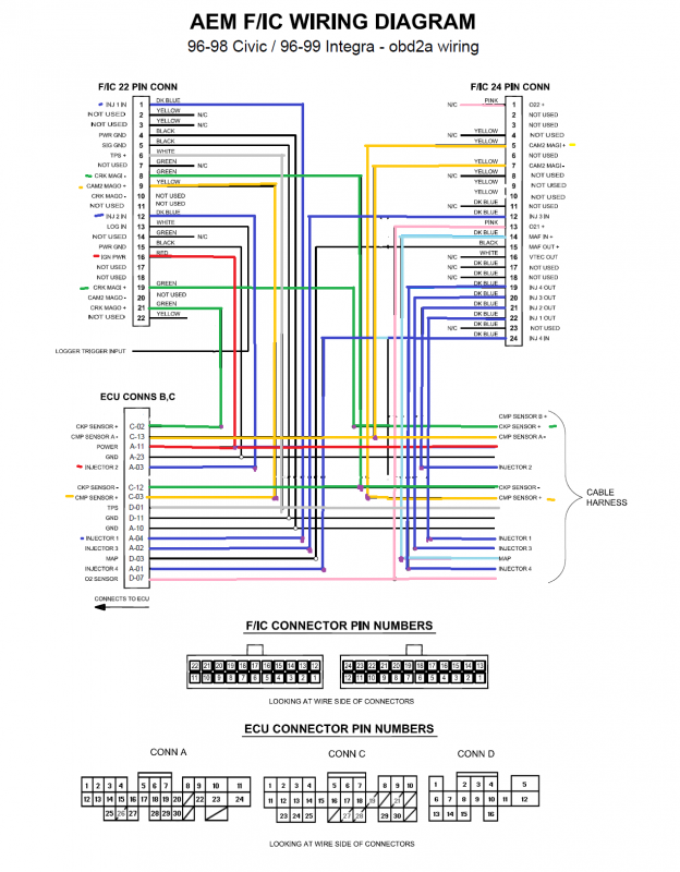
Here is the wiring diagram for an OBD2a Honda Civic. This diagram can be adapted to work on obd1 or obd2b civic. That would be 92-00.
If you don’t think you can cut and solder all the wires then get a boomslang plug and play hardness for your car. They est around $160 to $250
Diagram
![Image]()
Start with just the tapping wires. Then move on to the Injectors wires, then cam,crank.
Work with 1 wire at a time and be sure to look at the IN/OUT of the wires on the FIC.
Remember the injectors wires are IN from ECU and OUT to INJ.
While the Cam and Crank wires are IN from SENSOR and OUT to ECU.
Once all that is done. Put in the bypass harness and start your car. Your car should start like normal without problems.
If it doesn’t then check your wiring you messed up somewhere.
Part 2 Setup\\\\
This is for setting up the basic setting for the AEM FIC. This is for getting your car to run OEM (NO turbo, supercharger or bigger injectors).
Open up the AEM software. I use version 3.05.
Once open you will need to see what the Firmware on the FIC is.
Go to File > Get slave version. Then follow the on screen steps.
I find that the obd2 civics like to run the fuel firmware “z104.hex”
Each firmware is different but the basic is z104 for normal injectors, z107 was an improvement on that. Then z110 was for scion and batch fire injection.
Not we will move on to the settings.
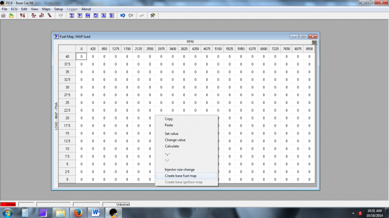
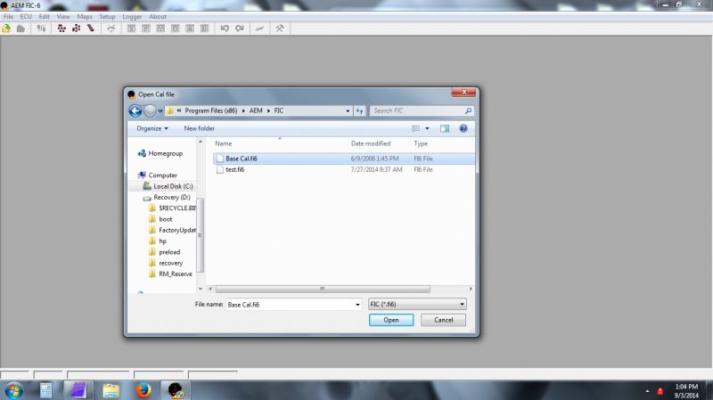
Click the File > Open
Then browser to where your base_cal.fi6 (should be in your aem fic program folder)
![Image]()
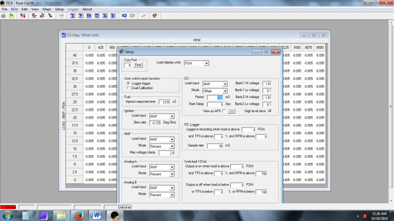
Then click settings (the hammer and wrench icon)
These are the default settings.
![Image]()
Basically your setting should match mines. For a 92 – 00 d15/d16 civic. If your using a different type of civic of car all together then read the notes on the settings.
![Image]()
First note that you can load the cal file to the AEM FIC even if its not on or plug into the car. Simple plug the usb cable to the port and install the drivers. Then your be able to update the file anytime your connected.
Settings break down\\\\\\\
Left to bottom to right to bottom.
Switch input function > You can pick if you want to use this wire to do on board logging
or use dual maps. With dual maps your be able to have 2 tunes and
flip between them by grounding out this wire.
Fuel Injector response time > This is the injector dead on time. I will get into this more
but for stock injectors left this at 486.
Ignition > Simply this just sets up what sensor you want to use to make your table.
The load input should be MAP and Slew rate 0.125
MAF > Load input should be switch to MAP, This will use the build in map sensor of
the FIC.
Mode - should be in Percent.
Max voltage clamp – This is the maximum voltage that the build in map sensor
should ever see NA. The easiest way to find this is to install t
the FIC hook it up to the laptop and turn the key on the car.
Don’t start it just turn it to get readings.
Click the gauge Icon (- + looking thing). It will bring up the
gauges and your get some data.
Look for MAF voltage.
Hondas should be 2.8 volts for map sensor and 3.8 for MAF.
There is guides online for setting up the MAF clamping map. I didn’t have to deal with that so I don’t good first hand on that. But basically you need to do a 3rd or 4th gear pull while NA stock, From 2k to Redline. You will want to datalog the highest MAF voltage you get. Then your input that number into the MAF clamp.
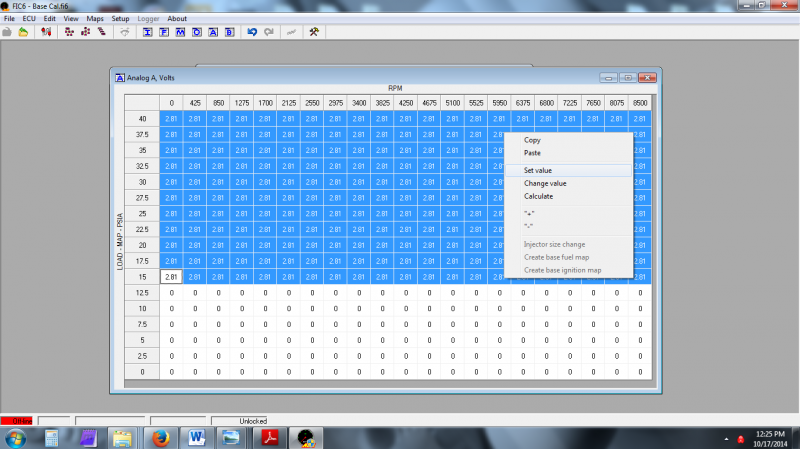
Analog A/B > This is use if you have other sensors that need to be fooled. I know if your car has a MAF and MAP sensor. Then your MAF sensor will be wires to the MAF wires of the FIC and your MAP sensor wires will go to Analog A.
You would then need to set up a clamp for that.
Put Analog A to Load MAP and Voltage, Then make a map like this.
Basically where there is boost it will output 2.8 volts
![Image]()
Load display Units = PSIA. REMEMBER!!!! 14.7psia is = 0inhg. So 15psia is really 0.3psi.
24psia = 9.3psi (this is what your see on your boost gauge.)
Then 5.3psia = 20in hg.
Hopefully you get an understanding of how psia is gauged.
O2
Load should be MAP (again will use the build in FIC map sensor for its table)
Mode – This should be in offset. I’ll get into this in a minute.
Period- 100ms. Ill get into to later
Start Delay – The amount of time to wait before it starts to adjust the o2 readings.
Banks 1 / 2 hi and low – This is For your front o2 sensors left and right if you’re a V motor (not VTEC but V6 or V8, or even inline 6.)
High level drive Check.
FIC logger > These are the settings for the internal logger. It will only log data when the switch is flip and the settings are met. The sample rate is how fast it can record. There is a chart somewhere on how long it can record but the basic of it is it will record for about 10 sec.
Switched 12v DC. > This is a programmable 12 volt output. Depending on who you wire it up you can set it up for vtec control or anything else your can thing of. Mines is setup for over boost warning. It is hook up to a 12volt led and when I go over my program boost the light comes on.
The output on is when you want it to turn on
Output off is when it should turn back off once its been turn on.
i.e. over boost for 10psi.
On 24.7psia, 1 TPS, 1rpm…
Off 24psia, 0 TPS, 0 rpm………This will turn the light on when the boost is at 10psi (your boost gauge reading) and turns it off when it drops to around 9.3psi
Feel free to use the guide but please dont copy and paste it else where. If you do give me the credit thats due.
Part 1 Install\\\\
Here is the wiring diagram for an OBD2a Honda Civic. This diagram can be adapted to work on obd1 or obd2b civic. That would be 92-00.
If you don’t think you can cut and solder all the wires then get a boomslang plug and play hardness for your car. They est around $160 to $250
Diagram
Start with just the tapping wires. Then move on to the Injectors wires, then cam,crank.
Work with 1 wire at a time and be sure to look at the IN/OUT of the wires on the FIC.
Remember the injectors wires are IN from ECU and OUT to INJ.
While the Cam and Crank wires are IN from SENSOR and OUT to ECU.
Once all that is done. Put in the bypass harness and start your car. Your car should start like normal without problems.
If it doesn’t then check your wiring you messed up somewhere.
Part 2 Setup\\\\
This is for setting up the basic setting for the AEM FIC. This is for getting your car to run OEM (NO turbo, supercharger or bigger injectors).
Open up the AEM software. I use version 3.05.
Once open you will need to see what the Firmware on the FIC is.
Go to File > Get slave version. Then follow the on screen steps.
I find that the obd2 civics like to run the fuel firmware “z104.hex”
Each firmware is different but the basic is z104 for normal injectors, z107 was an improvement on that. Then z110 was for scion and batch fire injection.
Not we will move on to the settings.
Click the File > Open
Then browser to where your base_cal.fi6 (should be in your aem fic program folder)
Then click settings (the hammer and wrench icon)
These are the default settings.
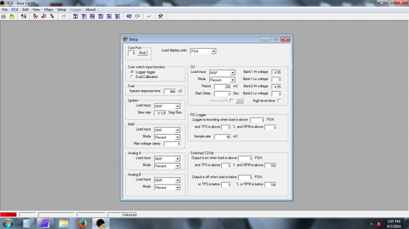
Basically your setting should match mines. For a 92 – 00 d15/d16 civic. If your using a different type of civic of car all together then read the notes on the settings.
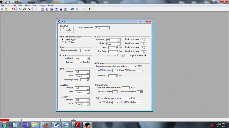
First note that you can load the cal file to the AEM FIC even if its not on or plug into the car. Simple plug the usb cable to the port and install the drivers. Then your be able to update the file anytime your connected.
Settings break down\\\\\\\
Left to bottom to right to bottom.
Switch input function > You can pick if you want to use this wire to do on board logging
or use dual maps. With dual maps your be able to have 2 tunes and
flip between them by grounding out this wire.
Fuel Injector response time > This is the injector dead on time. I will get into this more
but for stock injectors left this at 486.
Ignition > Simply this just sets up what sensor you want to use to make your table.
The load input should be MAP and Slew rate 0.125
MAF > Load input should be switch to MAP, This will use the build in map sensor of
the FIC.
Mode - should be in Percent.
Max voltage clamp – This is the maximum voltage that the build in map sensor
should ever see NA. The easiest way to find this is to install t
the FIC hook it up to the laptop and turn the key on the car.
Don’t start it just turn it to get readings.
Click the gauge Icon (- + looking thing). It will bring up the
gauges and your get some data.
Look for MAF voltage.
Hondas should be 2.8 volts for map sensor and 3.8 for MAF.
There is guides online for setting up the MAF clamping map. I didn’t have to deal with that so I don’t good first hand on that. But basically you need to do a 3rd or 4th gear pull while NA stock, From 2k to Redline. You will want to datalog the highest MAF voltage you get. Then your input that number into the MAF clamp.
Analog A/B > This is use if you have other sensors that need to be fooled. I know if your car has a MAF and MAP sensor. Then your MAF sensor will be wires to the MAF wires of the FIC and your MAP sensor wires will go to Analog A.
You would then need to set up a clamp for that.
Put Analog A to Load MAP and Voltage, Then make a map like this.
Basically where there is boost it will output 2.8 volts
Load display Units = PSIA. REMEMBER!!!! 14.7psia is = 0inhg. So 15psia is really 0.3psi.
24psia = 9.3psi (this is what your see on your boost gauge.)
Then 5.3psia = 20in hg.
Hopefully you get an understanding of how psia is gauged.
O2
Load should be MAP (again will use the build in FIC map sensor for its table)
Mode – This should be in offset. I’ll get into this in a minute.
Period- 100ms. Ill get into to later
Start Delay – The amount of time to wait before it starts to adjust the o2 readings.
Banks 1 / 2 hi and low – This is For your front o2 sensors left and right if you’re a V motor (not VTEC but V6 or V8, or even inline 6.)
High level drive Check.
FIC logger > These are the settings for the internal logger. It will only log data when the switch is flip and the settings are met. The sample rate is how fast it can record. There is a chart somewhere on how long it can record but the basic of it is it will record for about 10 sec.
Switched 12v DC. > This is a programmable 12 volt output. Depending on who you wire it up you can set it up for vtec control or anything else your can thing of. Mines is setup for over boost warning. It is hook up to a 12volt led and when I go over my program boost the light comes on.
The output on is when you want it to turn on
Output off is when it should turn back off once its been turn on.
i.e. over boost for 10psi.
On 24.7psia, 1 TPS, 1rpm…
Off 24psia, 0 TPS, 0 rpm………This will turn the light on when the boost is at 10psi (your boost gauge reading) and turns it off when it drops to around 9.3psi